
The sensitive areas inside a DAC
Three regions deserve particular attention.
Clock and reference conditions
Digital samples need the correct value and timing. Noise around the clock can affect phase-noise behaviour, while instability in reference conditions can contribute to conversion error. That is one reason MSB places critical clocking close to conversion rather than treating an external master clock as a mandatory final step for every product.
Conversion network
Whether a DAC uses a discrete ladder, another proprietary architecture or an integrated converter, it must turn precisely timed data into analogue current or voltage. Power distribution, grounding, local regulation, temperature and layout are therefore part of the conversion environment.
Newly created analogue output
After conversion, quiet harmonics and decaying notes share the signal with much larger musical peaks. A low noise floor helps preserve the available range between those quiet sounds and the circuit’s own noise.
The engineering target is not merely the absence of an audible fault. It is an environment quiet and stable enough that the recording, rather than the device, defines the smallest usable signal.
How interference can couple into the analogue result
Separating digital and power sections gives the designer more control over several paths:
- Conducted noise can travel through power rails and shared ground impedance as processors, rectifiers and regulators draw changing current.
- Radiated interference can arise from transformers, display activity, network processing and fast digital edges.
- Mechanical and thermal effects can come from transformer vibration, local hot spots and temperature-sensitive precision components.
- Clock-related noise can increase when the oscillator and its supply share an unfavourable electrical environment.
Moving a power supply into another enclosure does not make these mechanisms disappear. DC connections and grounding still have to be designed well. Separation provides distance and allows current loops, shielding, cooling and component placement to be managed with fewer compromises.
What the Reference Powerbase contributes
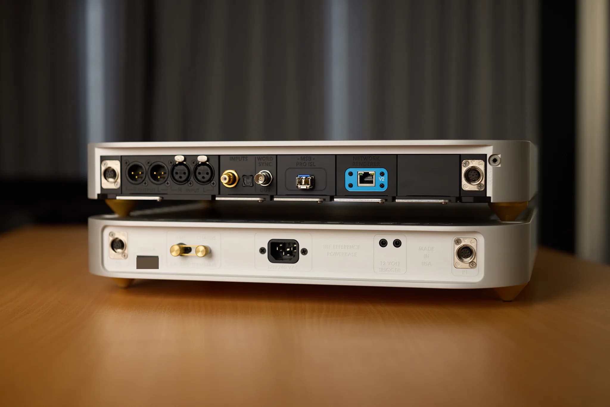
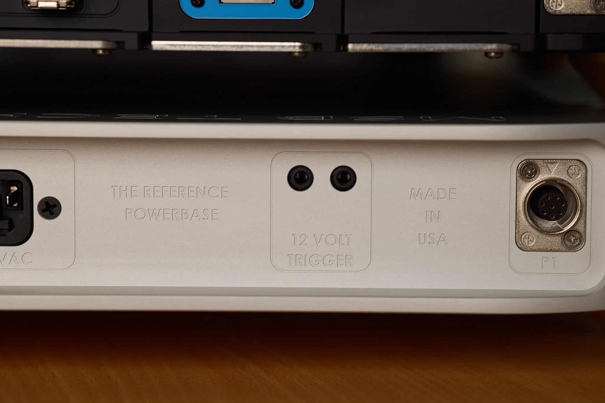
The Reference Powerbase supplies the DAC as part of its original design. MSB’s official Reference specification lists a dedicated Powerbase, two Hybrid power cables and a ground cable.
The separate enclosure moves large power-supply components and their associated magnetic, mechanical and thermal activity away from the Reference conversion chassis. It also frees internal space in the DAC for the clock, Hybrid modules, output network and modular inputs.
That does not mean a third-party linear supply is equivalent. The result depends on the complete relationship between transformer, rectification, local regulation, grounding, cabling and chassis layout.
Cascade: separate processing, conversion and power
Cascade makes the division easy to see.
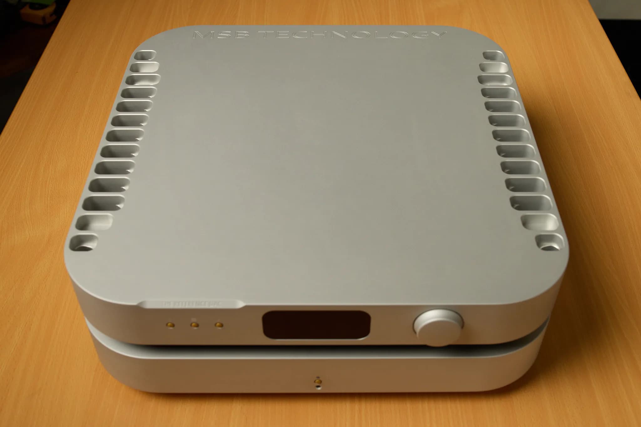
The Digital Director handles sources, interfaces, display and intensive digital processing. A fibre-based Cascade-Link carries conversion-ready data to the Analog Converter without a conductive path for upstream electrical noise. The Analog Converter contains eight Hybrid DAC MKII modules, a Femto clock and passive analogue stages. A dedicated Powerbase supports the analogue electronics.
MSB also places the display in its own shielded CNC pocket and synchronises its refresh to the audio clock. Whether every implementation detail is audible in a given room is a separate listening question; the architecture itself has a clear purpose: electrically noisy functions are kept away from the low-noise conversion environment.
Palisade: power and conversion in one chassis
Palisade retains a Digital Director and separate Analog Converter but integrates the linear power supply into the converter chassis. MSB describes extensive internal shielding and layout work intended to protect the conversion process.
Integrating the supply reduces the number of chassis while making internal shielding and layout more important. It offers a different balance of size, cost and electrical separation.
That distinction matters when evaluating any multi-box product. Ask what has been separated, what remains together and how the connection between enclosures is handled.
Power architecture and passive output meet at the analogue stage
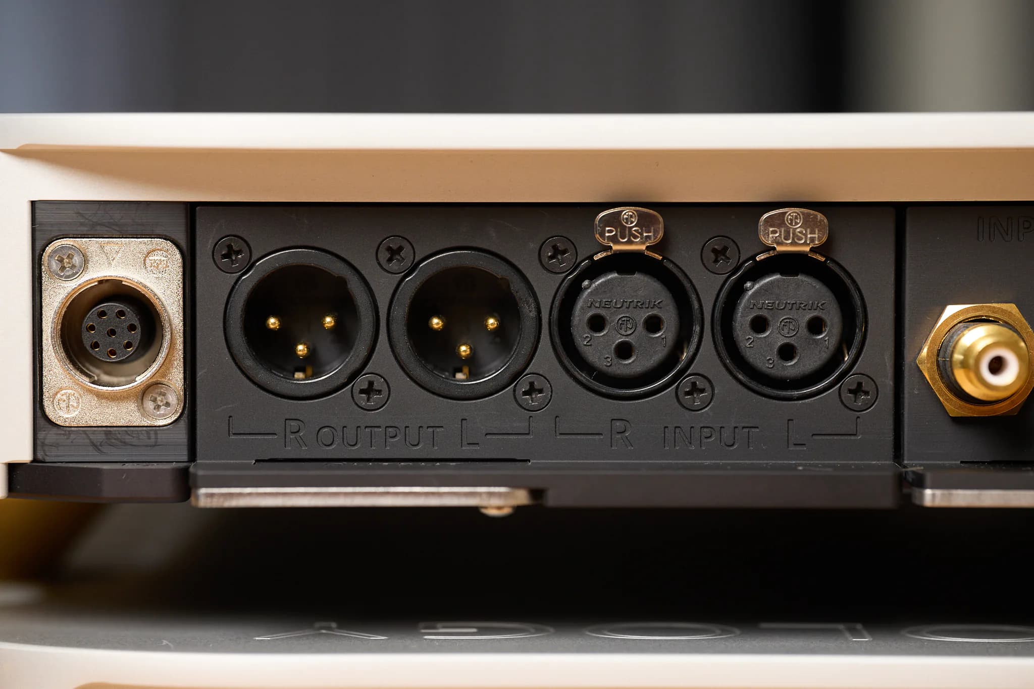
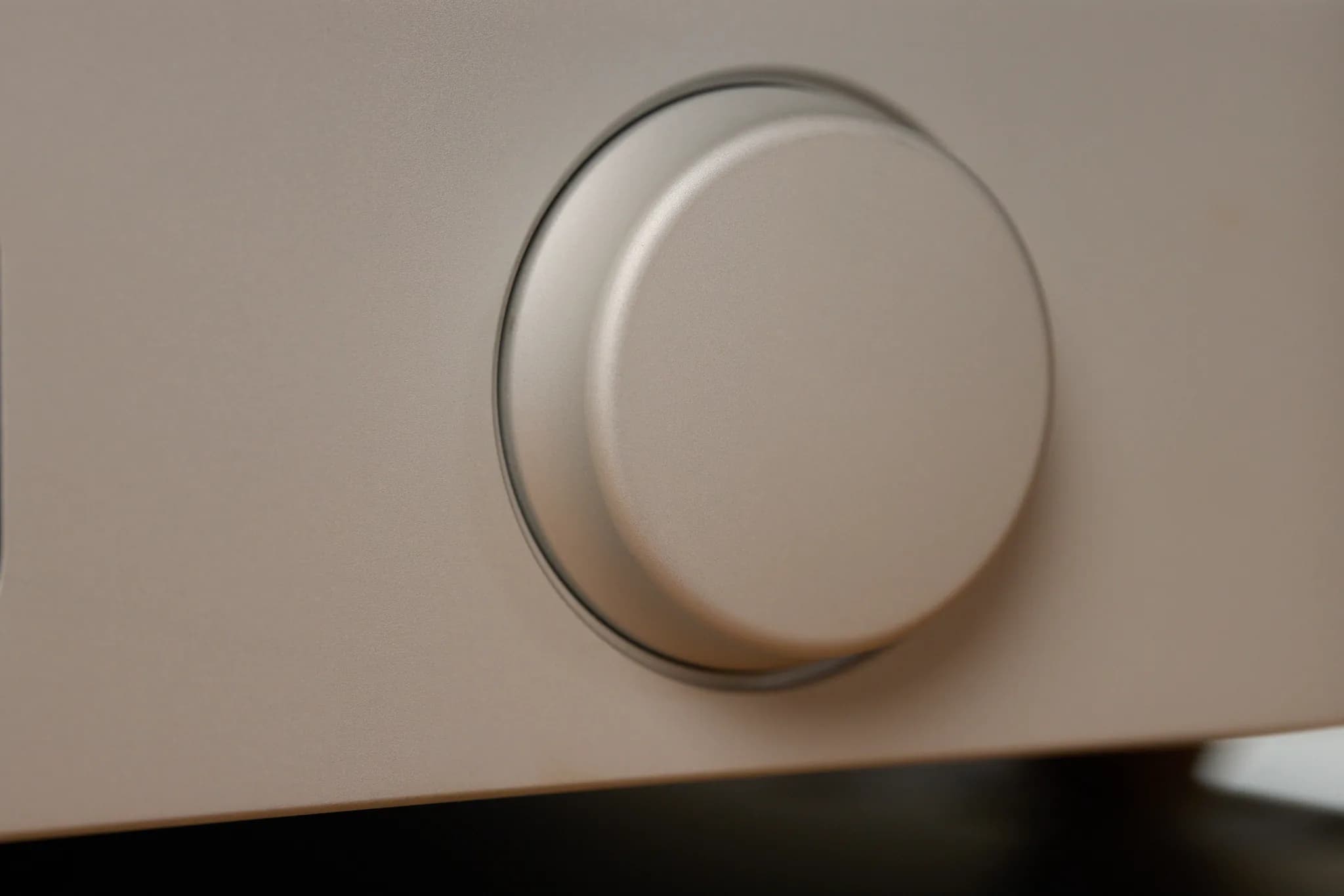
MSB’s Hybrid modules produce an analogue voltage without a conventional active buffer after conversion. In the Reference, the optional preamplifier output attenuates that signal through a passive, constant-impedance network in 1 dB steps. MSB specifies 150-ohm balanced output impedance and 3.57 Vrms maximum from a digital input.
The system can therefore be simplified from DAC, active preamplifier and power amplifier to DAC and power amplifier, if the electrical and functional requirements allow it.
When the system has enough gain and does not need the switching or buffering of a separate preamplifier, the DAC’s volume control can simplify the installation. It can also reduce the number of chassis, power supplies and interconnects needed.
Digital volume, passive analogue attenuation and active gain
The three common approaches solve different problems.
Digital volume before conversion
The numerical level is reduced in the digital domain. Modern high-precision processing can perform this extremely well, so the old claim that every reduction simply “throws away bits” is too crude. At very low levels, however, the relationship between digital signal level and the DAC’s fixed downstream analogue noise still depends on the product’s internal architecture.
Passive analogue attenuation after conversion
The DAC completes conversion at full level, then reduces the resulting analogue signal. This avoids another active gain stage, but a conventional passive control can present changing output impedance and become sensitive to cables and load. MSB’s constant-impedance network is designed to make that relationship more stable.
Active preamplification
An active preamplifier can provide gain, buffering, low output impedance, long-cable drive, source switching and multiple outputs. Those capabilities require another active circuit and power system, which must be engineered not to obscure the source.
None of the three is universally correct. The decision follows function, load and listening result.
When direct connection is worth testing
A Reference owner should consider a technically appropriate direct comparison when:
- the power amplifier has suitable input sensitivity and impedance;
- interconnects are reasonably short;
- no additional active gain is required;
- the DAC can provide all necessary source switching;
- the system does not require several independently driven outputs.
In the system used for this series, bypassing the Burmester 232 preamplifier revealed more microdynamic continuity and decay without making the balance thin or cold. A later informal session with ten listeners and several integrated amplifiers also favoured the direct route in that specific comparison. It was not a controlled scientific test, so it is best treated as corroborating listening experience rather than proof.
When a separate preamplifier remains the better tool
Keep or add an active preamplifier when the system needs analogue source switching, phono or tape integration, long balanced runs, several outputs, low-impedance load drive, extra gain or a particular tonal and dynamic contribution.
A fine active preamplifier can add scale, density and control while preserving most of the source’s transparency. The relevant test is not ideological minimalism. It is whether the preamplifier’s electrical and musical contribution is greater than what the additional stage removes.
How power, isolation and output work together
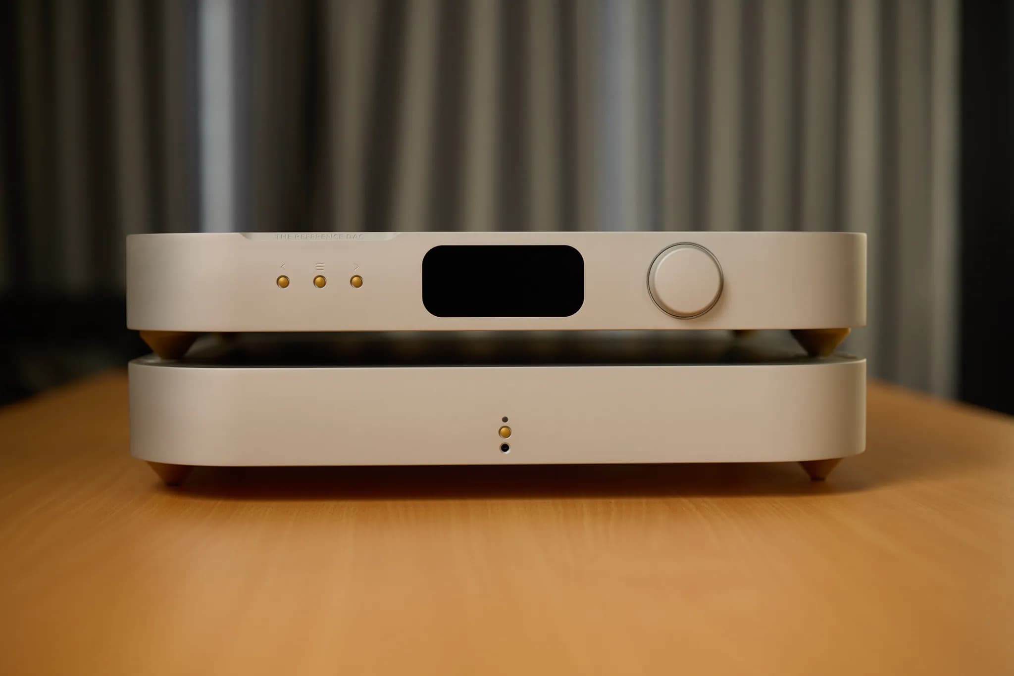
The Powerbase supplies the DAC, optical links separate digital equipment electrically, and passive attenuation controls output level. Together, these choices limit interaction with conversion and reduce the need for an additional active output stage.
To decide whether direct connection suits your system, compare it using your intended amplifier, cables and listening levels. Include the source switching and output connections you need.
Read the complete MSB Reference DAC review or request an MSB private audition.